DAY 20
Summary of Topics
Covered in Today’s Lecture
NOTE
– THIS PAGE USES SOME ANIMATION, AND CONTAINS A SUB-PAGE.
IT WILL NOT PRINT VERY WELL.
Mechanical
Oscillations and Sound Waves
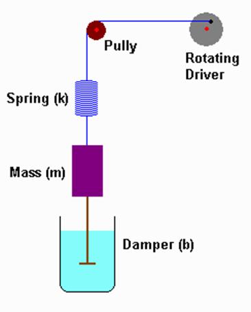 A mechanical oscillator consists of a spring,
a mass that oscillates, a damper, and a driving
force. These are the components of any
mechanically oscillating system.
A mechanical oscillator consists of a spring,
a mass that oscillates, a damper, and a driving
force. These are the components of any
mechanically oscillating system.
If
we look at this system from an energy standpoint, we see that each component
plays a distinct role:
·
The
driver puts energy into the system.
·
The
spring stores energy in the form of elastic potential energy. The spring stores the greatest energy when
the mass is not moving.
·
The mass
stores energy in the form of kinetic energy.
The mass contains the greatest energy when it is moving at maximum speed.
·
The
damper takes the energy in the system and turns it into heat.
Thus a mechanical oscillator consists of a driver that putting energy into the system, energy oscillating between elastic potential energy and kinetic energy, and energy leaving the system via heat through the damper.
If the oscillator is in a medium that will support sound waves, such as air, the oscillating mass pushes the air back & forth, serving as a source for sound waves. The sound waves radiate out from the oscillator, taking some of the energy of the oscillator with them (thus the air acts as a damping mechanism, too).
|
|
This animation
shows sound waves radiating outward from an oscillating mass. Note that in this animation the oscillating
mass moves horizontally. |
All
of these are present in something that makes sound, such as a violin
string. The string has mass. The string also has elasticity (which plays
the role of the spring). Air and various
frictions within the instrument play the role of a damper. The bow that is drawn across the violin
string is the driver. When a musician
draws the bow across the string, he drives the system to oscillate. The oscillations of the string serve as the
source of sound waves which radiate outward from the instrument.
Electromagnetic
Oscillations and Waves
What about an electrical equivalent of this mechanical oscillation that serves as a source for mechanical (sound) waves? Can we have electrical or magnetic oscillations that serve as a source for electrical or magnetic waves?
The answer is yes. In fact, we have already discussed electrical devices that play roles similar to the roles played by springs and dampers.
|
Mechanical |
|
Electrical |
|
Damper -- turns mechanical
energy into heat. Damping action
depends on damping coefficient and motion of the mass that is being damped. F = - b v = - b (Dx/t) In calculus terms: F = - b v = - b (dx/dt) |
|
Resistor -- turns electrical
energy into heat. Voltage drop across
a resistor depends on resistance and the motion of charge (i.e. current). U
= I R = R (DQ/t) In calculus terms: U = I R = R (dQ/dt) |
|
Spring -- stores energy,
regardless of whether it is compressed or extended. Energy storage depends on amount of spring
deformation, not on motion. F = - k x
|
|
Capacitor – stores energy,
regardless of which plate carries positive or negative charge. Energy storage depends on amount of charge,
not on motion of charge. U = Q/C = (1/C) Q |
In
this analogy we are building, it appears that there are many analogous
quantities:
|
Mechanical |
|
Electrical |
|
Force (F) |
is analogous to |
Voltage (U) |
Damping coefficient (b)
|
is analogous to |
Resistance (R) |
Spring Constant (k)
|
is analogous to |
The inverse of Capacitance (1/C) |
Position (x)
|
is analogous to |
Charge (Q) |
Velocity (v = Dx/t)
(or
v = dx/dt in calculus terms)
|
is analogous to |
Current (I = DQ/t) (or I = dQ/dt in calculus terms) |
What is missing? Something that plays the role of the mass -- that stores energy due to motion.
Well, for the mass the relevant equations are
F
= m a which is F = m (Dv/t)
|
|
|
|
In calculus terms this is
|
and
E
= ½ m v2
So
by analogy we expect this missing electrical factor that is analogous to m
(we’ll call the missing factor L) to have the relevant equations of
U = L (DI/t)
|
In calculus terms this is
U = L (dI/dt) = L d2Q/dt2
|
and
E
= ½ L I2
This
mystery factor L exists. It is called inductance,
and it completes our analogy:
|
Mechanical |
|
Electrical |
|
|
Force (F) |
|
Voltage (U) |
|
Damping coefficient (b)
|
F = -bv |
Resistance (R) |
U = RI |
Spring Constant (k)
|
F = -kx E = ½kx2 |
The inverse of Capacitance (1/C) |
U = (1/C)Q E = ½(1/C)Q2 |
Position (x)
|
|
Charge (Q) |
|
Velocity (v = Dx/t)
|
|
Current (I = DQ/t) |
|
Mass (m)
|
F = m(Dv/t) E = ½mv2 |
Inductance (L) |
U = L(DI/t) E = ½LI2 |
Note,
our analogy helped us get the equation U = L(DI/t).
However, the equation is incomplete, as we will see soon.
Electromagnetic
Induction
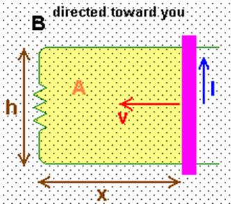
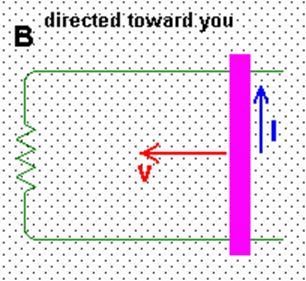
 What
is induction? Consider the picture at
right. The purple bar is conducting and
is in contact with the green circuit wire.
What
is induction? Consider the picture at
right. The purple bar is conducting and
is in contact with the green circuit wire.
As the bar moves to the left with speed v, positive charges are forced upward through the bar by the force the B field exerts on them via
F = qv x B
and the Right-Hand-Rule. This creates a current I that runs counter-clockwise through the circuit. Since there is a current, there must be a potential difference (voltage) that appears in the circuit due to the motion of the bar. This is called an induced voltage.
 In general it is
found that current is induced in a circuit any time the magnetic flux
through the circuit changes. The
magnetic flux FB
is the product of the B-field and the area of the circuit. It can be expressed as a DOT product
In general it is
found that current is induced in a circuit any time the magnetic flux
through the circuit changes. The
magnetic flux FB
is the product of the B-field and the area of the circuit. It can be expressed as a DOT product
FB = B.A
where B is the field vector and A is a vector than points perpendicularly to the plane of the circuit and represents the area of the circuit (A = h x in the figure above). However, if the plane of the circuit is perpendicular to the field this is just
FB = BA
The induced voltage in the circuit is given by the rate of change of the flux
|
Uinduced = - DFB/t |
In calculus terms |
This is known as Faraday’s Law of Induction and it says that any time there is
![]() a
change in flux through a circuit, whether it is due to a change in the
circuit’s dimensions (as in the case of the purple sliding bar), or
a
change in flux through a circuit, whether it is due to a change in the
circuit’s dimensions (as in the case of the purple sliding bar), or
![]() a
change in the strength of the B-field, or
a
change in the strength of the B-field, or
![]() a
change in the relative orientation of the field and the circuit,
a
change in the relative orientation of the field and the circuit,
a voltage will be induced in the circuit.
Click here for the induction demo program used in class.
Induction Resists
Change
|
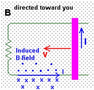
Consider the
picture at right again. Because the
area of the circuit is decreasing the flux is decreasing. A current is induced in the circuit flowing
counter-clockwise. |
|
|
|
The induced
current then creates its own magnetic field.
This induced field acts to reinforce the existing field -- note the
direction of the induced field as given by the Right-Hand-Rule. Therefore, while the motion of the bar
decreases the area of the circuit, decreasing the flux, the induced current
creates a magnetic field which increases the flux! |
In other words, the induction acts to oppose change in flux. If the bar were moved in the opposite direction, the flux would increase. However, the induced current would flow clockwise, creating an induced field that opposed the existing B field and hence decreasing the flux.
It is a general rule that induction always acts to oppose change. That is why there is a negative sign in Faraday’s Law. The “induction always acts to oppose change” rule is known as Lenz’s Law.
Inductance
The connection between Faraday’s Law and the inductance “L” value that we arrived at earlier is fairly easy to see in the case of a solenoid.
A while back we discussed solenoids. We learned that the magnetic field created by a solenoid is
|
|
Solenoid
viewed from side. |
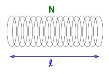
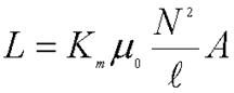
Where
Km is called the relative permeability of the material in the
core of the solenoid, N is the number of turns in the solenoid, l is the length of the solenoid, I is the current through the solenoid, and m0
is the permeability of free space.
The
flux through a solenoid then is
|
Where A is the cross-sectional area of the solenoid. The N term shows up because there is flux through each loop in the solenoid. |
Solenoid
viewed from end. |

Combining
our equations for magnetic field and flux we get
|
Note – in the discussion below,
non-calculus versions of the equations are on the left; calculus versions are
on the right highlighted in yellow. So long as the
current flowing through the solenoid is steady, no voltage is induced. However, if the current is changed, the
Faraday’s Law kicks in: |
||
|
|
|
|
|
Among all these
terms, only the current varies. The
rest are all either the dimensions of the solenoid or physical constants: |
||
|
|
|
|
|
The quantity in
brackets is the inductance L of the solenoid
|
||
|
and the induced
voltage is |
||
|
|
|
|


The
negative sign, which we did not have in our earlier derivation of inductance by
analogy, indicates that Lenz’s Law is present in the solenoid – the induced voltage always acts to oppose
change in current.
 Example Problem #1
In the picture at left, h = 5 cm, x = 7 cm, the bar
is moving to the left at v = 10 m/s, B = 5 T directed perpendicular the plane
of the circuit, and the resistance in the circuit is 0.1 W.
a) Calculate the magnetic flux.
b) Calculate the current
induced in the circuit.
c) Calculate the force required
to move the bar at that speed.
Solution:
A = .05 m x .07 m = .0035 m2
B = 5 T
FB = BA = 5 T (.0035 m2)
= 0.0175 Tm2
The flux is 0.0175 Tm2.
Now let’s get the induced current. First I’ll figure the induced voltage:
Uinduced = - DFB/t
= - B(DA/t)
A = hx so this is now
Vinduced = - Bh(Dx/t)
= - Bhv
= - 5 T (.05 m)
(10 m/s)
= - 2.5 Tm2/s
Let me work out the units on that:
[T]m2/s = [N/Am]m2/s
= [N/A]m/s = (Nm)/(As) = J/C = Volt
So, keeping in mind the fact that the negative sign just
indicates that induction opposed change, the induce voltage in the circuit is
2.5 V.
So the current induced is
Iinduced = Vinduced/R = 2.5 V/0.1 W = 25 A
25 A of induced
current appear in the circuit.
What about the force F required to move the bar at v = 10
m/s?
Well, I know from Physics I that
F v = Power
I also know that in a circuit
Power = I V
The power from the force must be what goes into making
current flow in the circuit, so
F v = I V
F (10 m/s) = (25 A)(2.5 V)
F (10 m/s) = 62.5 VA = 62.5 [J/C][C/s]
F (10 m/s) = 62.5 J/s
F = 6.25 J/m = 6.25 Nm/m = 6.25 N
It takes 6.25 N of
force to move the bar. It takes work to
generate electric current!
Example Problem #2
Inductance is measured in units of Henrys. What is a Henry, in terms of more basic
units?
Solution:
N has no units – it is just a number. Ditto for Km. The SI units for A would be m2. m0 has units of Tm/A
according to one book I looked up the value in, N/A2
according to another.
l is measured in m. We’ll work out both versions:
|
Version
with Tm/A |
Version
with N/A2 |
|
|
|
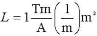
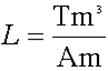
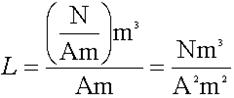

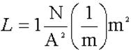
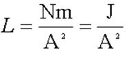
So it seems a Henry
is a Joule per square Ampere.
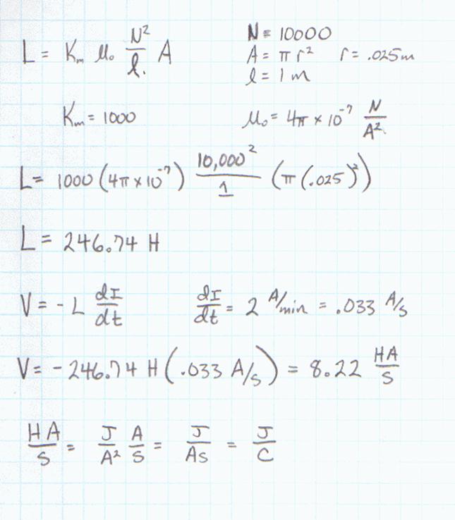
Example Problem #3
A solenoid has diameter 5 cm, length 100 cm, and
contains 10,000 turns of wire. It has a
core with relative permeability 1000.
Find the inductance of this solenoid.
What voltage will be induced on it if current through the solenoid
increases at a rate of 2 A per minute?
Solution:
|
|
I
gather together my information and plug it into the inductance equation for a
solenoid. Since I just worked out the
units for this in the previous example, I’m leaving units out. |
|
The
rate of change of the current is 2 A in one minute. |
|
|
I’ll
work through these units. |
|
|
|
|
|
And my final answers are that the
solenoid has an inductance of 247 H and when current is increased through it
at a rate of |
|